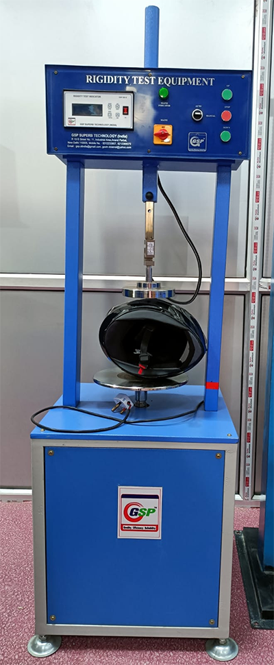
The helmet shall be tested by the method prescribed in 7.3.2 and shall meet the following requirements:
7.3.1.1 Along each axis, the deformation measured under the 630 N load shall not exceed by more than 40 mm than that measured under the initial 30 N load. 7.3.1.2 After restoration of the 30 N load, the deformation measured shall not exceed by more than 15 mm than that measured under the initial 30 N load. 16
7.3.2.1 The helmet, after undergoing ambient temperature and humidity conditioning shall be placed between two parallel plates by means of which a known load can be applied along the longitudinal axis (1) (line LL in the Fig. 4 ) or the transverse axis (line TT in the Fig. 4). The surface of the plates shall be large enough to contain a circle of at least 65 mm in diameter. An initial load of 30 N shall be applied at a minimum plates speed of 20 mm/min, and after two minutes the distance between the plates shall be measured. The load shall then be increased by 100 N at a minimum plate speed of 20 mm/min and then wait for two minutes. This procedure shall be repeated until the application of a load of 630 N.
(1) During the test along the longitudinal axis the contact point between the helmet and one of the two plates must be the `B’ impact point. 7.3.2.2 The load applied to the plates shall then be reduced to 30 N at a minimum plate speed of 20 mm/min and kept at that value for five minutes, the distance between the plates shall then be measured.
7.3.2.3 The helmet used for the test along the longitudinal axis shall be a new helmet and another new helmet shall be used for the test along the transverse axis.
